
Introduction
Ever felt confident about a motor choice — then watched it fail under load? That scenario plays out in factories and workshops more often than leaders admit. An electric motor sits at the heart of machinery; roughly 30–40% of unplanned downtime traces back to poor motor selection or mismatched control systems (industry surveys back this up). So how do we stop throwing time and money at the same avoidable problems?
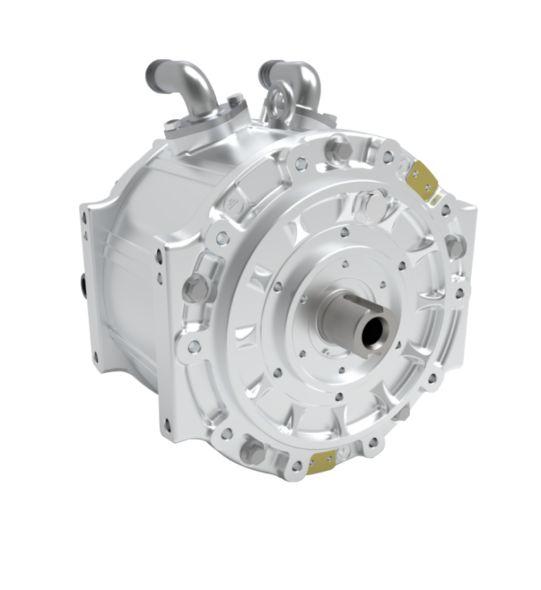
I’ll walk you through common traps, backed by simple data and real-world scenarios — and I’ll be blunt where vendors and specs hide the complications. We’ll touch on torque curves, inverter sizing, and control algorithm headaches in plain terms. Ready to dig in? Let’s move from the surface issues to the root causes.
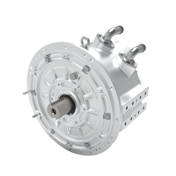
Why Traditional Solutions Fail for the permanent magnet synchronous motor
What’s the real issue?
When I evaluate projects, I see the same patterns. Engineers pick a permanent magnet synchronous motor for its efficiency and compact size, then assume the rest will follow. The reality: mismatched inverters, undersized power converters, and crude control algorithms often negate the motor’s advantages. Torque ripple, thermal hotspots at the rotor-stator interface, and poor field-weakening management show up after installation — not on paper. Look, it’s simpler than you think: a perfect motor on paper still needs correct drive electronics and good thermal design.
Traditional fixes focus on over-specifying hardware — bigger inverters, thicker shafts, heavy-duty encoders. That approach hides two deep flaws. First, it treats symptoms (overheating, vibration) rather than the control loop that created them. Second, it increases cost and mass unnecessarily. I’ve recommended smaller, smarter systems that pair a matched inverter and refined PWM strategy with the motor’s torque-speed profile. This reduces wasted energy and lowers peak stress on bearings and windings. This is technical, yes — but also practical: measure the torque demand curve, then pick a controller that supports field weakening and soft current limits. You’ll cut failures and keep the design compact.
Case Example and Future Outlook for electric motors in Precision Applications
What’s Next?
I want to share a brief case: we helped a packaging plant swap out oversized induction motors for a matched permanent magnet synchronous motor and a modern inverter. The new setup used an adaptive control algorithm and reduced peak torque by smoothing acceleration ramps — downtime dropped by nearly half. The plant also gained energy savings and less mechanical wear. — funny how that works, right?
Looking forward, I expect more emphasis on digital twin testing and smarter drive tuning. Edge diagnostics and better encoder feedback will let teams tune control loops remotely and spot rotor heating before it becomes a failure. From my view, the future isn’t about bigger motors; it’s about smarter pairing — control, firmware, and thermal design working together. Three quick evaluation metrics I always share when advising clients: 1) match the motor’s torque-speed curve to real load profiles; 2) ensure the inverter supports advanced PWM and field-weakening; 3) verify thermal paths and serviceability (bearings, stator cooling). Use these to compare vendors and avoid common over-spec traps. I’ve seen the results — measurable uptime improvements and lower lifecycle cost.
We’ve covered selection mistakes, control shortcomings, and a path forward. If you want a practical next step, I recommend running a short load-profile test and discussing inverter options early in the design phase — it pays off. For those exploring verified components and matched drives, consider exploring product and support options at Santroll.